16. INDUCTION_SOURCE_FIELD Namelist
The INDUCTION_SOURCE_FIELD namelist defines the external magnetic field that serves as the applied source in the computation of Joule heat for induction heating simulations. The field is a continuous wave (CW) function with frequency \(f\) of the form
is the superposition of a uniform field of strength \(A\) oriented in the unit direction \(\hat{e}\), and the magnetic fields \(\vec{h}_i\) generated by a collection of induction coils with electric currents \(c_i\).
Besides a steady CW source that is used for an entire induction heating simulation, a CW source that changes abruptly at a sequence of heat transfer times \(t_1,\ldots,t_n\) may be defined by specifying addtional values for the source parameters (\(f\), \(A\), and \(c_i\)) to use at those times.
Namelist Usage
- Required/Optional:
Required when the induction_heating PHYSICS option is enabled.
- Single/Multiple Instances:
Single
16.1. Namelist Variables
orientation
The orientation \(\hat{e}\) of the uniform field. For simplicity this is currently restricted to one of the coordinates axes, \(\hat{x}\), \(\hat{y}\), or \(\hat{z}\). This value also defines the orientation of the induction coil axes.
- Type:
string
- Default:
“z”
- Valid Values:
“x”, “y”, or “z”
times
An optional list of one or more heat transfer times \(t_1<\ldots<t_n\) when the CW source field changes.
- Type:
real
- Default:
none
- Valid Values:
any strictly increasing sequence
- Notes:
When this is specified, corresponding lists of values must also be specified for frequency, uniform_strength, and the current component of each coil defined by coils. The number of values in those lists must be one more than the number of values specified here.
frequency
The frequency \(f\) (cycles per unit time) of the sinusoidally-varying source field. When times is specified, additional values to use at each of those times must also be specified.
- Type:
real
- Default:
none
- Valid Values:
any sequence of one or more postive values
uniform_strength
The strength \(A\) of the uniform source field. The field is oriented in the direction specified by orientation. When times is specified, additional values to use at each of those times must also be specified.
- Type:
real
- Default:
0
- Valid Values:
any sequence of one or more values
- Notes:
A negative value essentially shifts the phase by 180 degrees.
For reference, the magnitude of the magnetic field within an infinitely-long, finely-wound coil with linear current density \(I\) is simply \(I\). The field magnitude at the center of a circular current loop of radius \(r\) with current \(I\) is \(I/{2r}\). In both cases the field is directed along the axis of the coil/loop.
coils
Optional data that defines the geometry and current of one or more induction coils. Figure 16.1.1 shows the idealized model of a coil that is used to analytically evaluate the magnetic field it generates. This parameter is a structure array. Each element defines a coil and consists of the following components. Note that the axis orientation is defined by the orientation parameter above and is common to all coils.
Component |
Description |
|---|---|
%num_loops |
The number of current loops. |
%radius |
The radius \(r>0\) of the coil loops. |
%length |
The length \(l>0\) of the coil. This is only required when the number of coil loops is greater than 1. |
%center |
A 3-vector giving the position of the center \(x_0\) of the coil; the default is 0, 0, 0. |
%current |
The amplitude \(c_i\) of the sinusoidally-varying current in each coil loop. A negative value essentially shifts the phase by 180 degrees. When times is specified, additional values to use at each of those times must also be specified. |
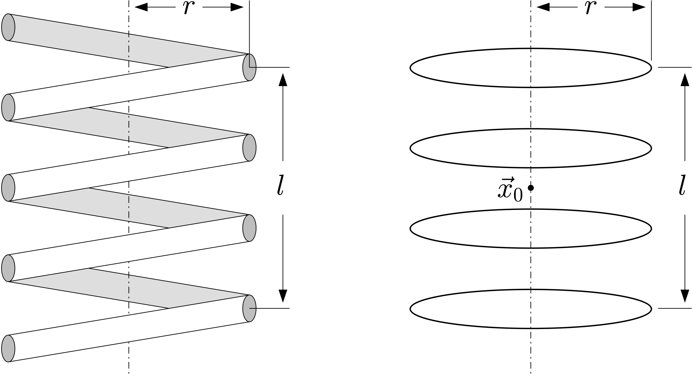
Figure 16.1.1 Physical 4-turn helical coil with extended wire cross section (left), and its idealized model as a stacked array of circular current loops (right).