Vertex Anchor Cluster (VAC)
Warning
The VAC algorithm is intended for development and not recommended for regular users. For best results, use one of the other algorithms.
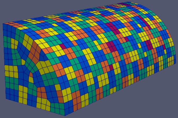
Result of VAC on a quarter cyclinder.
The Vertex Anchor Cluster (VAC) patching algorithm is based on the observation that the set of all faces sharing a particular vertex (the faces of a vertex) tend to form patches with desirable properties. Such patches are connected, relatively small, and tend to be roughly circular. These patches have an associated ‘vertex anchor’, namely the vertex shared by all their faces. We use the term ‘full patch’ to refer to patches consisting of all the faces of their vertex anchor. ‘Partial patches’, conversely, refers to patches whose faces are a strict subset of the faces of their vertex anchor. The VAC algorithm attempts to maximize the number of full patches generated.
Algorithm
The VAC algorithm begins by iterating through each vertex and adding its corresponding full patch to a global priority queue. The queue entries are then popped one by one until the queue is empty. If all the faces of a queue entry are unassigned, a new patch is created from the entry. Otherwise, VAC makes a new entry from the subset of faces of the original entry that are still unassigned, and adds that entry to the queue. Once the queue is empty, we have a valid patching of the enclosure. Finally, VAC merges patches where possible, in accordance with the VAC_MERGE_LEVEL namelist parameter.
Outline
The following is a high-level outline of the VAC algorithm.
Initialization
Generate the vface array that maps a vertex to the faces of that vertex.
Generate the face adjacency matrix. Faces at angles greater than MAX_ANGLE are not adjacent.
Generate the boundary boolean array that records whether a vertex is on the boundary of an enclosure component.
Patch Assignment
For each vertex \(V_j\) of the enclosure, define a patch \(P_i\) that consists of all the faces of \(V_j\). Add the tuple \((P_i, V_j)\) to a global priority queue with weight \(E(P_i, V_j)\).
Call SET_PATCHES(TRUE)
Patch Merging
If VAC_MERGE_LEVEL >= 1 then:
Call SPLIT_PATCHES()
For each vertex \(V_j\), check if the faces \(V_j\) fully contain two or more patches. If so, unassign all the faces of \(V_j\), re-queue all the enclosed patches with their original weight, and queue a new patch \(P_i\) consisting of the faces of \(V_j\) with weight \(E(P_k,V_j)\).
Call SET_PATCHES(TRUE)
If VAC_MERGE_LEVEL >= 2 then:
Call SPLIT_PATCHES()
For each vertex \(V_j\), find its neighboring vertices (those connected to \(V_j\) by an edge). For each neighbor \(V_n\) of \(V_j\), let \(F\) be the union of the faces of \(V_j\) and \(V_n\). Check if \(F\) fully contains two or more patches. If so, unassign all faces in \(F\), re-queue all the enclosed patches with their original weight, and queue a new patch consisting of \(F\) whose vertex anchor is \(V_j\) if it is not a boundary vertex, and \(V_n\) otherwise.
Call SET_PATCHES(FALSE)
If VAC_MERGE_LEVEL >= 3 then:
Repeat step 3.2, but add a large constant to the original weight of the enclosed patches before queueing them.
Subroutines
SET_PATCHES(re-queue)
While the priority queue is not empty:
Pop the tuple \((P_i, V_j)\) of least weight from the queue.
If all of the faces \(F_k\) of \(P_i\) are unassigned, then assign all the faces to a new patch.
Otherwise:
If re-queue is TRUE, then for each connected subset of faces \(P_k \subset P_i\) that are unassigned, create a new tuple \((P_k, V_j)\) and add it to the queue with weight \(E(P_k, V_j)\).
SPLIT_PATCHES()
For each patch \(P_i\) with less than VAC_SPLIT_PATCH_SIZE faces, unassign all the faces of \(P_i\), queue these faces as 1-face patches, and re-queue \(P_i\) with its original weight.
Connected Components
During initialization, the VAC algorithm constructs the face adjacency graph of the enclosure. This graph defines the connected components of the enclosure, and is used to quickly determine connected subsets of queue entry faces.
The face adjacency graph is defined by the topology of the mesh and the MAX_ANGLE namelist parameter which controls the maximum allowable angle between the (normals of) adjacent faces. Specifically, two topologically adjacent faces at a angle greater than MAX_ANGLE will not share an edge in the adjacency graph. The connected components of the face adjacency graph thus represent collections of faces that are bounded by ‘sharp’ edges (angles greater than MAX_ANGLE) or the mesh boundary itself.
The face adjacency graph defines a set of boundary vertices, namely the vertices incident on edges along the boundary of a component. These boundary vertices play a role in both computing the weight of queue entries.
Note
Throughout this document we use the terms ‘enclosure components’ or simply ‘components’ as a short-hand for refering to the connected components of the face adjacency graph.
Patch Weight
Each entry of the global priority queue has an associated weight which determines their order in the queue. The VAC queue prioritizes entries with a lower weight, so the lowest weight patches are assigned first.
Let the tuple \((P_i, V_j)\) denote the patch \(P_i\) with vertex anchor \(V_j\). The weight \(E\) of a patch \((P_i, V_j)\) is given by the error metric:
The terms of \(E(P_i,V_j)\) are discussed in detail below.
Normal Bias
We want patches to be roughly planar so that all their faces have similar views of the rest of the enclosure. This ensures that the patch view factor is a reasonable approximation of the view factors of its faces.
We use the \(\mathcal{L}^{2,1}\) metric defined by Cohen-Steiner et al. [1] to measure the planarity of a patch. The \(\mathcal{L}^{2,1}\) metric is based on an \(\mathcal{L}^2\) measure of the normal field over the patch. Given a patch \(P_i\) with normal \(\vec{n}_i\) we define
where \(\vec{n}_i(x)\) is the normal at the point \(x \in P_i\).
Given that \(P_i\) is a set of faces, we discretize the \(\mathcal{L}^{2,1}\) metric of \(P_i\) as
where \(\vec{n}_k\) is the normal of face \(F_k \in P_i\) and \(\vec{n}_i\) is the normalized area-weighted average of the face normals. In other words, \(\vec{n}_i\) is the normalized vector
where \(w_k\) is the area of face \(F_k \in P_i\).
Notice that in our discretization of the \(\mathcal{L}^{2,1}\) metric we omit multiplication by the face areas, so its not a true approximation of the integral. We do this to give equal weighting to all faces in a patch. Without this correction, small (in area) faces could be at large angles to the other faces in the patch, but the patch might still have a low \(\mathcal{L}^{2,1}\) metric. Moreover, we normalize by the number of faces \(\lvert P_i \rvert\) to give all patches a similar weight. Without this normalization, patches with more faces tend to have a greater weight than smaller patches, regardless of their planarity.
We define the normal bias of patch \(P_i\) as its discretized \(\mathcal{L}^{2,1}\) metric:
Since the largest deviation between the patch normal \(\vec{n}_i\) and a face normal \(\vec{n}_k\) is when these vectors are antiparallel it follows that \(0 \le E_{normal}(P_i) \le 4\) for any patch \(P_i\).
Shape Bias
We want to prioritize patches that are as circular as possible to ensure that all their faces have similar views of the rest of the enclosure. In particular, long skinny patches are more likely to have shadow discontinuities fall across them.
We use the irregularity metric defined by Garland et al. [2] to measure the compactness of a patch. Given a patch \(P_i\) with area \(w\) and perimeter \(\rho\), the irregularity \(\gamma\) of the patch is defined as
A circle has irregularity \(\gamma=1\) and larger values of \(\gamma\) correspond to more irregular (less compact) regions. It is possible to have patches with \(\gamma < 1\) if the patches have large internal curvature (e.g. patches spanning a corner). This does not occur in practice because VAC avoids disconnected patches and the maximum angle between connected faces tends to be small (see the MAX_ANGLE namelist parameter reference).
We define the shape bias of patch \(P_i\) as its irregularity:
Size Bias
We want to maximize the number of patches generated, and therefore must discourage 1-face patches as much as possible. However, 1-face patches tend to have a low weight in the above metrics, since individual faces are fairly compact (low \(E_{shape}\)) and their \(E_{normal}\) bias is 0.
We define a size bias for a patch \(P_i\) as:
We set \(E_{size}(P_i)=4\) for 1-face patches because \(E_{normal}(P_i) \le 4\). In effect, this means that VAC considers a 1-face patch to be as bad as a highly distorted patch.
Full Patch Bias
We want to maximize the number of full patches generated, because such patches tend to have desirable properties. Moreover, we want to discourage partial patches, as they can have arbitrarily bad shapes and prevent full patches from being formed elsewhere.
Thus, we define a full patch bias for a patch \(P_i\) with vertex anchor \(V_j\) as follows:
Position Bias
Vertices on the boundary of enclosure components are poor vertex anchor candidates. The faces of boundary vertices can span more than one component, and connected subsets of such faces tend to form badly shaped patches. For example, the faces of a vertex on the boundary between two enclosure components will form two patches, one in each component, and these patches will likely have a suboptimal shape, since they are essentially partial patches relative to a vertex in the component interior. Moreover, the faces of a vertex on the mesh boundary form a full patch with \(E_{size} = 0\), despite their suboptimal shape.

Top: Two enclosure components meet at a boundary. A vertex on that boundary is labeled in red. The faces of the red vertex form two patches, colored grey and numbered. These grey patches are poorly shaped. Conversely, the blue patches formed by the blue vertices in the interior of each component are full patches with a desirable shape. Bottom: The red vertex is on the mesh boundary, and its faces are colored gray. These faces form a poorly shaped patch, despite it being a full patch (it includes all the faces of its vertex anchor). Note that the grey patch is a partial patch relative to the yellow vertex. The blue vertices in the interior of the component form full patches with a desirable shape.
Therefore, we want to heavily bias against patches with a boundary vertex as their anchor. We define a position bias for a patch \(P_i\) with vertex anchor \(V_j\) as follows:
We set \(E_{pos}\) to such a high value for boundary vertices because, as discussed above, the faces of such vertices tend to form suboptimally shaped patches. So why not avoid boundary vertices altogether? We need to queue boundary vertices to handle the corner case where an enclosure component is only one face wide. Such a component has no interior vertices! Thus, ignoring boundary vertices would leaves those faces without a patch assignment. Our definition of \(E_{pos}\) allows us to cleanly handle the corner case, while making sure that boundary vertices are not used unless absolutely necessary.
Patch Merging
After the patch assignment step of the VAC algorithm, all faces are assigned to a patch. However, we may still reduce the patch count by merging patches together. Therefore, VAC implements several patch merging subroutines of increasing aggressiveness. To ensure the resulting merged patches are well-formed, the merge subroutines will only create full patches.
In order to increase the number of merge candidates, all the merge subroutines begin by ‘splitting’ small patches. The effects of patch splitting are discussed briefly below.
The VAC_MERGE_LEVEL namelist parameter controls the aggressiveness of patch merging. VAC currently support four merge levels. They are described in detail below.
Patch Splitting
All the merge subroutines begin by ‘splitting’ small patches. The idea here is to increase the number of merge candidates by providing more 1-face patches. The small patches aren’t technically split, rather they are deleted and added back to the queue with their original weight. Each patch’s constituent faces are also added to the queue as 1-face patches.
The small patches are re-queued so that they will be reassigned if none of their faces are used. This makes sure that splitting does not produce unnecessary 1-face patches. If no merges occur, then the enclosure is left in the same patch configuration as before the split.
Note that the 1-face patches will have a large weight and thus are only used to ‘fill-in the gaps’ between the newly merged patches. The 1-face patches are needed because some of the merge subroutines do not re-queue connected subsets of a queue entry’s faces (see the VAC outline section ). The 1-face patches ensure that all faces are assigned to a patch at the end of the merge procedure.
The VAC_SPLIT_PATCH_SIZE namelist parameter determines the maximum size of patches to be split. Patches with up to VAC_SPLIT_PATCH_SIZE faces are split.
Merge Level 0
No merging is performed. The algorithm terminates immediately after the patch assignment stage.
Merge Level 1
Merge patches that are within the faces of a vertex.
For each vertex \(V_j\), let \(F_j\) be the faces of \(V_j\) and check whether \(F_j\) fully encloses two or more patches. If so, then the enclosed patches can be safely merged into a new full patch with \(V_j\) as a vertex anchor. Thus, we delete the enclosed patches and add the \((F_j, V_j)\) to the queue with weight \(E(F_j, V_j)\).
Although unlikely, it is possible for some of the enclosed patches to have a lower weight than \(F_j\). Thus we also add the enclosed patches back to the queue with their original weight. The merge will only happen if \(F_j\) has a lower weight than all of the enclosed patches.
Merge Level 2
Same as Merge Level 1. Additionally, merge patches that are within the faces of pairs of adjacent vertices.
For each vertex \(V_j\), find all its vertex neighbors, i.e. those vertices connected to \(V_j\) by an edge. For each neighbor \(V_n\) of \(V_j\), let \(F\) be the union of the faces of \(V_j\) and \(V_n\). Check whether \(F\) fully encloses two or more patches. If so, then the enclosed patches can be safely merged into a new patch. To avoid an unnecessarily high weight, we choose as vertex anchor whichever of \(V_j\) or \(V_n\) is not a boundary vertex. If neither is on the boundary, we chose \(V_n\) as anchor. Finally, we delete the enclosed patches and add \((F, V_k)\) to the queue with weight \(E(F, V_k)\), where \(V_k\) is the previously determined vertex anchor.
Note that the patch \(F\) is different from all other patches discussed so far in that \(F\) consists of the faces of two vertices. Such patches have similar properties to full patches, but are larger and may not be as circular. Despite their less desirable shape, such patches are still admissible for the purposes of solving the radiosity problem.
Since full patches are generally preferred, we also add the enclosed patches back to the queue with their original weight. Thus, the merge will only happen if \(F\) has a lower weight than all of the enclosed patches. Note that \(F\) will tend to have a low weight, since \(E_{size}(F) = 0\) and \(E_{full}(F,V_k)=0\) regardless of the choice of vertex anchor \(V_k\). Therefore \(F\) will not tend to replace full patches that are fairly planar and compact, but will tend to replace incomplete patches patches and irregular full patches.
Merge Level 3
Same as Merge Level 2. Additionally, merge patches that are within the faces of pairs of adjacent vertices, but add a large constant to the weight of the enclosed patches.
We repeat the same procedure as for Merge Level 2, but in this case we add a large constant \(c=100\) to the original weight of the enclosed patches before adding them back to the queue. The idea here is that we want to always replace the enclosed patches with the merge candidate \(F\).
So why add the enclosed patches to the queue in the first place? It’s possible for two merge candidates to have some faces in common. When one of the candidates is assigned, its faces are no longer available for the second candidate. If we did not re-queue the enclosed patches of the second candidate, then some of its faces would remain unassigned.
Note that Merge Level 3 implies Merge Level 2. Thus the ‘faces of vertex neighbors’ merge is executed twice, once with and once without the added constant to the enclosed patch weight. We do this so that the merge candidates with a lower weight than their enclosed patches are assigned before all other candidates.
Namelist Parameters
The PATCHES namelist allows a user to configure the VAC algorithm parameters. Although the PATCHES namelist supports many parameters, only four are used by VAC, and only two of those are unique to VAC.
The general parameters used by VAC are VERBOSITY_LEVEL and MAX_ANGLE. Refer to the PATCHES namelist documentation for more information on those parameters.
The four parameters unique to VAC are all prefixed with VAC. These have already been discussed, so we’ll only touch on them briefly here and link to the previous discussion.
VAC_MERGE_LEVEL
Controls the aggressiveness of patch merging.
Type:
INTEGERDomain: vac_merge_level >= 0
Default: vac_merge_level = 3
After the patch assignment stage, all faces are assigned to a patch. The algorithm then attempts to merge patches in order to reduce the patch count.
The merge levels are defined as follows:
Value |
Description |
|---|---|
vac_merge_level = 0 |
No merging. |
vac_merge_level = 1 |
Merge patches that are within the faces of a vertex. |
vac_merge_level = 2 |
Same as 1. Additionally, merge patches that are within the faces of pairs of adjacent vertices. The old patches are requeued with their original weight so that a merge is only performed if the merge candidate has a lower weight than any of its consituent patches. |
vac_merge_level >= 3 |
Same as 2. Additionally, merge patches within the faces of pairs of adjacent vertices, but add a large weight to the requeued old patches. This ensures that the merge is always performed. |
For a more details on each merge level, refer to the section on patch merging.
VAC_SPLIT_PATCH_SIZE
Defines the maximum size of patches to be split during patch merging.
Type:
INTEGERDomain: vac_split_patch_size > 1
Default: vac_split_patch_size = 3
Before merging patches, all merge subroutines find
patches with less than vac_split_patch_size faces and ‘split’ them into 1-face patches. The
original patches aren’t actually modified, rather they are re-queued along with their constituent
faces. This allows the algorithm to find more merge candidates and then ‘fill in the gaps’ with the
1-face patches.
The 1-face patches have a large weight, so they will only be used after all other patches are assigned. Therefore, the enclosure will tend retain the same patches as before the split, unless this is not possible due to a merge.
For a more details on this parameter, refer to the section on patch splitting.
Note
For best results, set vac_split_patch_size to 3 for quadrilateral meshes and to 5 for
triangular meshes. This avoids splitting too many patches.
Glossary
- boundary vertex
A vertex incident on an edge located along the boundary of a connected component of the face adjacency graph. Such an edge is either on the mesh boundary, or between two faces at an angle greater than MAX_ANGLE.
- faces of a vertex
The set of all faces that have a particular vertex of the enclosure mesh as one of their vertices.
- full patch
A patch consisting of all the faces of its vertex anchor. Such patches tend to have desirable properties such as connectedness, a small (topological) size, and a roughly circular shape. VAC attempts to maximize the number of full patches generated.
- partial patch
A patch whose faces are a strict subset of the faces of its vertex anchor.
- vertex anchor
A special vertex that defines a patch. A patch with a given vertex anchor consists of a subset of the faces of that vertex.
References
David Cohen-Steiner, Pierre Alliez, and Mathieu Desbrun. Variational Shape Approximation. In ACM SIGGRAPH 2004 Papers, SIGGRAPH '04, 905–914. New York, NY, USA, 2004. ACM. doi:10.1145/1186562.1015817.
Michael Garland, Andrew Willmott, and Paul S. Heckbert. Hierarchical Face Clustering on Polygonal Surfaces. In Proceedings of the 2001 Symposium on Interactive 3D Graphics, I3D '01, 49–58. New York, NY, USA, 2001. ACM. doi:10.1145/364338.364345.